Potential and Limitations
During the last two decades of commercial wind turbine development one of the most obvious trends has been the growth in the size of turbines and the rotor blades to drive them. Along with this the average rotor power loading has decreased to values about half those of ten years ago. Some of the recent turbines are new models especially designed for low wind speed regimes, but most of them are existing wind turbines equipped with larger and larger rotor blades. The following article gives some insight into the possibilities and limitations of such turbine derivatives and will pay particular attention to the need to alter other turbine components as a result of the increase in the rotor diameter.
By Albrecht Kantelberg and Roland Stoer, Managing Directors, WINDnovation Engineering Solutions, Berlin, Germany

By Albrecht Kantelberg and Roland Stoer, Managing Directors, WINDnovation Engineering Solutions, Berlin, Germany
While turbines up to 1MW dominated the 1990s, the 1.5–3.0MW class of wind turbines became mature in the 2000s. Recently, even larger machines of 6MW rated power and higher have been erected as prototypes, mainly for offshore use. The global pattern in turbine growth has been accompanied by another trend in the last few years, that of increasing the rotor diameter for any given turbine size (Figure 1). This trend is driven by the fact that in many countries the best sites for wind turbines have now been exploited and new installations have to be sited in places with comparatively low average wind speeds. An increased rotor size helps to maximise the capacity factor of the wind turbines and the energy yield of the wind farm, and to lower the cost of energy. Looking at the nominal rotor loading (W rated power/m2 swept area) over time, Figure 2 shows this trend very clearly. Especially for IEC class 3 wind turbines, the average rotor power loading has decreased to values around 200W/m2, which is about half of what was typical some ten years ago. Among these recent turbines, there are new models especially designed for such low wind speed regimes, but most of them are existing wind turbines which are equipped with larger and larger rotor blades. Such upgrades are relatively cheap compared to new developments, so they are favoured by turbine manufacturers and operators.
General Approach
It is common practice to use different rotor sizes on one type of wind turbine. This is done to adapt the configuration to different wind classes. During the product life this is mostly done to follow the trend towards bigger rotors and so to increase the lifetime of the specific product.
Typically it is the design target to realise this adaptation without major changes in the turbine. In a few cases even the rotational speed has been kept constant for different rotors, leading to an increase in tip speed proportional to the increase in blade length. Sometimes this is done because a gearbox change has to be avoided, or a change in rotational speed is simply impossible, or – for permanent magnet direct drive turbines – would result in a reduction in rated power.
Changing the rated rotor speed has strong and contradictory effects on the drive-train and the blades of a wind turbine.
For the drive-train it is obviously ‘the faster the better’. Higher rotational speed proportionally corresponds to lower torque, which helps to reduce costs on gearboxes or direct drive generators.
For rotor blades it is more complex. While high tip speeds lead to optimum aerodynamic efficiency, such high rotor speeds cause several difficulties. To avoid excessive noise and leading edge erosion there is a practical limit for the blade tip speed, so that most turbines operate in a relatively narrow band between 70m/s for low-noise onshore and some 90m/s for offshore turbines. Furthermore, high tip speeds, in combination with low rotor power loadings, lead to the need for very slender blades to avoid an excessive increase in thrust loads.
The solidity (= ratio of total rotor blade silhouette area/total swept area) is the parameter commonly used to evaluate the slenderness of a rotor blade. The blades required for wind turbines with a rotor power loading in the range of 200W/m² or below show a solidity below 3.5%, one-third of which is assigned to each of the three blades. This value has been cut by approximately 50% during the last few years (Figure 3).
The structural design of such blades is very challenging as there is very little room to fit in a sufficiently stiff and strong structure. Consequently, these blades are very flexible and difficult to control due to their excessive deflections in operation.
Scaling Up the Rotor Diameter – What Happens?
Rotor Aerodynamics
A typical engineering approach when developing new products of the same kind in a larger size is scaling up. It is assumed that the larger blades operate at the same rated power and have the same aerodynamic quality with regard to their maximum performance coefficient cp, and that the tip speed ratio (ratio between blade tip speed and wind speed) for the highest cp is similar. The scaling relationships are valid for steady-state flow without considering dynamic effects. In spite of these simplifications these relationships are useful to illustrate the principal trends. All relationships refer to the rotor swept area A.
When increasing the rotor diameter, the rated wind speed vrated is seemingly reduced in a strongly under-proportional way, but this is due to the cubic relationship between wind speed and wind power:
{tex}V_{rated, new} = V_{rated, old}\binom{A_{old}}{A_{new}}^{\frac{1}{3}{/tex}
At low wind speeds, when the rotor is operating at optimum tip speed ratio, the rotor thrust force is proportionally dependent on the rotor swept area. But the maximum thrust force and maximum blade out-of-plane bending typically occur at rated wind speed, when the turbine is running at full power but the pitch angle is still small.
When increasing rotor size, the decreasing rated wind speed causes the maximum thrust force FTmax and maximum blade bending moment MYBmax to grow at a slower rate than might be expected from the rotor size increase only:
{tex}F_{T.max,new} = F_{T.max,old}\binom{A_{new}}{A_{old}}^{\frac{1}{3}{/tex}
{tex}M_{YB.max,new} = M_{YB.max,old}\binom{A_{new}}{A_{old}}^{\frac{5}{6}{/tex}
As an example, an increase in rotor diameter of 23% leads to an increase in swept area of approximately 50%. In partial power operation at the same wind speed, according to the laws of scale, the bigger rotor will consequently generate 50% higher thrust load and a 86% higher blade root bending moment. But the rated wind speed will have been reduced by 14%, so the maximum thrust force increases only by 17% and the maximum bending moment MYB only by 40% compared to the smaller rotor (Figure 4). This under-proportional increase opens up some potential for the larger rotor diameter.
When increasing the rotor size without further technical restrictions one would keep the tip speed of the blades constant mainly because of noise. As discussed above, this results in a proportional reduction of rated rotational speed. The resulting (recommendable) new design tip speed ratio, which can be used as a measure for the slenderness of the new blade, can be derived:
{tex}\lambda_{new} = \lambda_{old}\binom{A_{new}}{A_{old}}^{\frac{1}{3}{/tex}
This relation shows that the design tip speed ratio increases strongly under-proportionally and to the inverse power of the tip speed. As the design tip speed ratio is a very convenient parameter to compare the operational behaviour of different rotor blades, it can be concluded that scaling up of the blade does not lead to a significant change in the general characteristics of the blade.
However, often the intention is to avoid changes in the drive-train, so the rated rotational speed should not be changed. In this case, the necessary increase in design tip speed ratio is much more relevant:
{tex}\lambda_{new} = \lambda_{old}\binom{A_{new}}{A_{old}}^{\frac{5}{6}{/tex}
Figure 5 shows these relations. To maintain similar operational behaviour for both rotors in the example above (50% increase in swept area) the blade design tip speed ratio l would need to be increased by about 14%, but if the tip speed remains the same the rotational speed will be reduced accordingly. This will result in the tip speed ratio (l) being increased by 40% where the rotational speed is being kept constant; consequently there will be a much more significant impact on the behaviour of the larger blades.
These calculations show that the potential to increase the rotor size while maintaining the rated rotational speed of the wind turbine is quite limited. The resulting high tip speeds will most probably result in unacceptable blade noise levels, as there is a feasibility limit for slenderness of the blades due to the required structural strength, the deflection requirements have to be observed (blade tip-to-tower clearance), and aeroelastic stability has to be ensured.
So, in most cases a balance between these conflicting targets has to be chosen: a slight increase in blade tip speed, a slight reduction in rotational speed, a consequential small increase in torque, might be acceptable to achieve an overall satisfactory turbine configuration.
Blade Mass and Mass Moment
When increasing the rotor diameter, typically the weight of the new blades is somewhat higher than the weight of the existing ones. While the pure laws of scale would suggest using a power of three to calculate the mass of the longer blades, the under-proportional increase in loads for a given turbine configuration and more sophisticated design methods and materials lead to the empirical value of 2.2–2.4 for the power of scaling up the mass of rotor blades. But the change in blade weight is often not very relevant to the overall tower top loads and dynamics, especially first tower eigenfrequency, as the blades are usually no more than 25% of the total tower top weight.
Much more important is the substantial increase in blade mass moment caused by the higher absolute mass in combination with the increased distance of the centre of gravity (COG) of the longer blades from the rotational centre. This mass moment is responsible for the biggest fraction of blade root in-plane fatigue loads. On multi-megawatt turbines, the edgewise fatigue loads are mostly driven by the design of the hub. As a consequence an increase of rotor diameter on bigger turbines often leads to hub fatigue problems and a redesign might be required.
Pitch Torque
Very long and slender blades tend to generate significantly higher blade root pitch torques than might be expected from aerodynamic scaling. Typically, the existing pitch drives have to deal with such load increases.
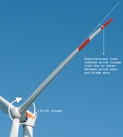
Such slender blades show relatively high deflections in operation due to their flexibility. Loads acting in the flapwise direction on the blade and at the same time perpendicular to the direction of deflection generate a blade root pitch torque due to the lever between deflected blade and pitch axis (Figure 6). When, for example, the blade is at the 3 o’clock position with strong flapwise deflection, the gravitational load generates a noticeable amount of blade root pitch torque.
In addition to this, the larger flapwise bending moment of longer blades and the larger edgewise bending moment due to the increased blade mass moment increase the pitch bearing friction. In situations when blade pitch torque and bearing friction torque add up, a significant increase in pitch drive torque will result and has to be dealt with.
As a consequence, the pitch system might be overloaded when longer and very slender blades are used and an upgrade of the pitch hardware is required to successfully operate the wind turbine in all conditions.
Blade Tip-to-Tower Clearance
Longer blades with increased flexibility tend not to fulfil the tip-to-tower requirements without taking further action. As typical deflections under high loads are in the range of 12–15% of their length (the higher end of the range for very slender blades), the absolute values most probably exceed the permissible margin for existing wind turbine configurations. As the nacelle geometry, including the tilt angle, can be considered fixed, increased pre-bending or a larger blade cone angle can be used to deal with this problem. In case these measures are not sufficient, the blade structure has to be stiffened by additional material, in most cases in the spar cap. This consequently increases the blade mass and adds to the loads. The imposed design modifications negate a part of the benefit of the larger rotor in terms of economic efficiency.
Wind Shear
When longer blades are used on existing turbines without a change in tower height, the relative variations in wind speed over the rotor diameter, bottom to top, increase. This causes significantly larger cyclic out-of-plane loads for the blades and a revolving hub bending moment.
Rotor Size Increase – Best Practice
If it has been decided to increase the rotor size for the reasons outlined above, an important decision needs to be taken as to whether the rated speed should or could be reduced. A reduction in rotor speed normally calls for a partial redesign of a direct drive generator or a change of the gearbox ratio in the case of a conventional drive-train. Usually the adaptation of the gearbox ratio is considered, while the other main components stay the same.
Moving down the structure from the rotor blades, through the turbine to the tower, it is noticeable that the load increase as discussed earlier is most serious for the blades themselves, the hub, the pitch drives and the pitch bearings. The other main components show comparatively lower changes in loads, which makes it much easier to keep them unaltered than for the components in the spinning system.
Regarding the components of the rotor, there are two basic strategies: keeping as much hardware as possible or upgrading or replacing the hub and pitch system.
Keeping as Much Hardware as Possible
This strategy uses all kinds of load-reducing measures to fit the loads from the new rotor into the allowable limits of the existing turbine components. In the case of a moderate rotor size increase, if there are noticeable strength safety margins in the turbine, and the turbine control system can be upgraded with advanced load-reducing features, this strategy might prove to be the most economic solution.
For a moderate increase in rotor size, the use of carbon fibre in the blade design can avoid some of the scaling problems as the blades are specifically more lightweight than glass-fibre blades. In many cases it is possible to maintain the mass moment of the former, shorter blades. So hub fatigue problems from in-plane loads can be avoided. Due to the high stiffness of carbon fibre, the deflections can be kept relatively low, helping to match the tip-to-tower requirements and to maintain acceptable blade pitch torques. But an increase in out-of-plane bending moment must still be expected due to the reduced gust damping characteristics of the less flexible carbon-fibre structure.
Upgrading or Replacing the Hub and Pitch System
When the pitch bearings and related bolt connections cannot handle the loads from the new blades any more, it is worth considering a completely new hub design, sometimes even including a bigger blade connection diameter.
For the 3MW class, the blade connection diameter of 2.3 metres has been a de facto standard since the days of the early blade designs with lengths in the range of 40 metres. For the biggest rotors in this class nowadays, with diameters of 120 metres and above, this blade connection diameter becomes a design bottleneck. Some turbine designers recently shifted to a blade connection diameter of 2.5 metres and beyond to deal with the higher load level. The resulting redesign of the cast hub makes it possible to deal with the increased blade root fatigue and extreme bending moments.
It is also possible to adapt the pitch system to the higher pitch torques experienced with the slender, flexible blades. The pitch control unit does not need to be changed, but the inverter, motor and gearbox might need replacement by stronger units. A suitable pitch bearing must be selected according to the loads of the upgraded configuration.
In the case of only a moderate increase in size and loads, the pitch bearing bolt circle diameters and the outer shape of the hub can be maintained and the sole hub modification that is needed is to change the wall thickness to deal with the increased loads. This minimises the changes on the cast mould and allows the use of the same spinner and other auxiliary units on the hub outside.
Conclusion
The strong trend towards larger blades for existing wind turbines affects the whole system. However, it is mainly the rotor consisting of the blades, the hub and the pitch drives that is directly affected by the resulting increase in loads; the effect on the other main turbine components is significantly smaller. Therefore, it appears reasonable not only to enlarge the blades but to consider the rotor as a subsystem subject to modification as a whole. This increases the flexibility for the designers as – for example – the blade root diameter can be changed according to the load requirements while the interface between hub and main shaft can be kept to avoid consequential changes in the nacelle. So the rotor change can be done very efficiently with regard to the optimisation of the complete wind turbine.