In the endeavour to reach zero emissions, one of the EU targets is to end the manufacturing of new vehicles that run on fossil fuel by 2035. This means that all new vehicles would be powered by other types of energy. On top of these are electric vehicles and fuel-cell vehicles. For a true zero emission, all energy required by these vehicles must be supplied by renewable energy (green hydrogen for fuel cell vehicles).
By Ahmad Hemami, McGill University, Montreal, Canada
At present, oil is the major energy source, and as it has been for many years, oil is transported from the source to consumer countries by oil tankers. Even if oil is used for commercial trucks and other purposes, the necessity for oil tankers will be greatly reduced.
On the other hand, renewable energy sources are not sufficiently available for all countries, and consequently there will be a need to transport energy from regions rich in renewable energy to consumers. The energy to be transported will be either electricity or, indirectly, hydrogen, because transportation of hydrogen by itself is difficult and costly (a significant percentage of hydrogen energy content is to be used for keeping it at a low temperature).
We may think that, thus, the tankers that currently transport crude oil will be modified to carry either electricity or ammonia, a potential candidate for hydrogen transportation. Electricity transportation at mega scale is in the form of battery energy storage systems (BESS), which are currently in large container units. Whereas ammonia is a liquid, these containers are individual units that could be interconnected. Anyhow, in both cases modifications must be made to the oil tankers.
Oil tankers come mainly in three sizes (1):
- Aframax class (approximately 80,000 to 120,000 Deadweight Tons [DWT]),
- Suezmax class (120,000 to 200,000 DWT), and
- Large Crude Carrier (VLCC) class, which ranges up to 320,000 DWT.
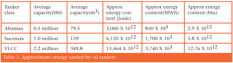
Deadweight tonnage is the maximum weight that a ship can carry and includes the weights of all facilities, fuel and personnel, as well as cargo. The average cargo volume capacity is given in table 1. Accordingly, cargo weight capacity can be determined from the crude oil density (800–900 kg/m³).
Based on the average heat value (energy content) of crude oil (42–47 MJ/kg), we may see the associated approximate energy carrying capacity of each class of tankers in Table 1.
Battery energy storage systems are essentially made up of many units of battery packs that are put in racks and placed in a container. It is necessary to supervise/monitor the performance of the batteries for safety, efficiency, electrical characteristics and cooling during both charging and discharging. At industrial level these container units can be put together for (theoretically) any capacity, provided that at this higher level a proper supervisory system takes care of the same technical issues as mentioned for the lower level.
In putting many BESS container units together, they are laid side-by-side on the ground. That is, these units are not placed on top of each other. On the contrary, to fit them in a ship they need to be mounted in multilevel arrangements. This may require stronger containers like those used in cargo ships. Here we would like to figure out how much electric energy can be carried by each tanker. Obviously, the limit for the number of containers that can be placed inside a ship is its weight and volume capacity. It is necessary to leave some space between BESS containers for accessing them as well as cooling. For this reason, we consider only 90% of the capacity of each tanker.
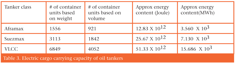
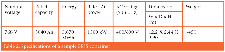
As an example of an air-cooled BESS unit in a 40ft container (2), we consider the one with the specifications in table 2. The results of how much electric energy can be carried by each tanker class are given in table 3. Obviously, these figures are very crude and can be far from real practical numbers. As shown, the number of units based on weight is much more than those based on volume. The electric capacities are, thus, based on the volume, which can go even lower due to layout limitations.
Further Reading
(1) TERMPOL Surveys and Studies, ENBRIDGE NORTHERN GATEWAY PROJECT, Section 3.9 Ship Specifications: https://iaac-aeic.gc.ca/050/documents_staticpost/cearref_21799/2559/section3_09.pdf
(2) https://nextgpower.com/product/containerized-energy-storage-system-bess-40-feet/

")